Creating Custom Symbols in EasyEda

There are ways to select components from the existing library in EasyEDA, and in the worst-case scenario, even if you can’t find the symbol within the library, there are hundreds of symbols contributed by users.
But it’s not really a safe bet to use others work without any verification, so we’ll see how we can build custom symbols not only by using manual methods but also by exploring how to use shortcuts like the symbol wizard and datasheet extraction to make the entire process super fast!

Creating Symbol
There are three ways to create symbol within EasyEDA Manual
Symbol Wizard
And, datasheet Extraction
First, we’ll start with the manual method to better understand all the tools and workflow for creating a symbol, and then move on to the other methods to reduce the time and effort required.
To start, go to Files > New and click on the symbol. Which would create a new symbol sheet.
Here, the tools are very similar to the one’s we are used to in the schematic editor’s drawing tools. Except for this additional pin tool for adding pins to the components,
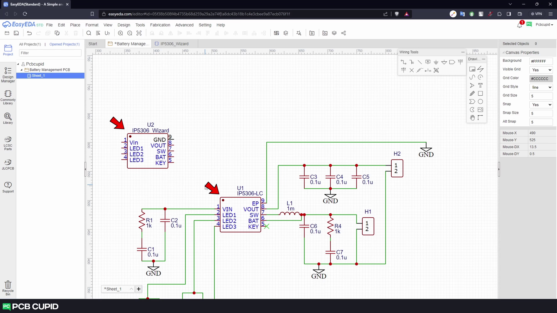
We can build any type of symbol we need, including ICs, transformers, and resistors, but to keep things simple, let’s start with replicating the IP5306 IC.
Since we are going to build an IC, let’s start with a rectangle.
Next, let’s add the pins using the pin tool.

Exploring Object Panel
The object panel on the right can be used to change the name and the pin number as per the datasheet.
For the spice property,set it to yes to display both the name and number of the pin. So, it’s visible in the schematic sheet.
The pin length will determine the size of the pin; let’s keep this at default 20. And in the pin placement, if you prefer accuracy over simplicity, you can simply use the X and Y coordinates to directly change the position of the pin instead of dragging around it with a cursor.
The next few options are for personalization, where you can change the pin color and the text color, but again, as preferred, its better to use the default settings of EasyEDA.
Then the next few options can help in setting the electrical properties of the pins, like mentioning the inverted signal pin with the dot properties or mentioning the clock signal of the IC. but IP5306 will not require both of these options. Then we have the electrical properties, which will help in defining the electrical property of the pin. In this case, we’ll set this Vin pin to Power Input, as this is the power that goes into the IC to charge the battery and also power the IC, according to the datasheet.
This completes the setup for the first pin

EasyEDA:Designing The Manual Symbol
Now, add the second pin. Follow the same process.
To slightly ease the process of entering values and pin numbers, we can also just double-click on a value and change it directly. However, we still have to use the properties panel for more options.
Anyway, it should give you an overall idea of how to create pins for your symbol in EasyEDA. So, let’s quickly add a few more pins and modify them as required.
This symbol looks good, so let’s save it by using the shortcut Ctrl+S and giving it a name.
Let’s call it the IP5306 manual’.
You can also provide other information like supplier details, supplier part numbers, manufacturer details, link to a datasheet, and more. Once done, hit save.
Since the symbol was created within this project, we would instinctively expect it to be within this project folder. But by default, this symbol will be stored in a global workspace, which can be accessed in all your projects.
Now to check if it’s actually located in the global library, Go to the library and make sure the search engine type is set to EasyEDA and the class is set to Workspace.
Here we can see the symbol we created with the name IP5306_manual.

EasyEDA: Customizing the Manual Symbol
Now let’s import this into the schematic and see how it looks.
but the first pin is missing.
because we had set the pin show properties to “no” So let’s go back to the symbol editor, fix the property to “yes,” and save the file.
Hmm, but the schematic is not updated yet, so to reflect the updated symbol, we need to right-click and select the option Update from Library.
This should update the symbol to the latest version.
The custom symbol is not as visually appealing as the one that we got from the LCSC library.
Of course, we can put more effort into making the symbol manually. So, it looks similar to the one from the supplier, but there is an easier way to do it.

EasyEDA: Designing By Using Symbol Wizard
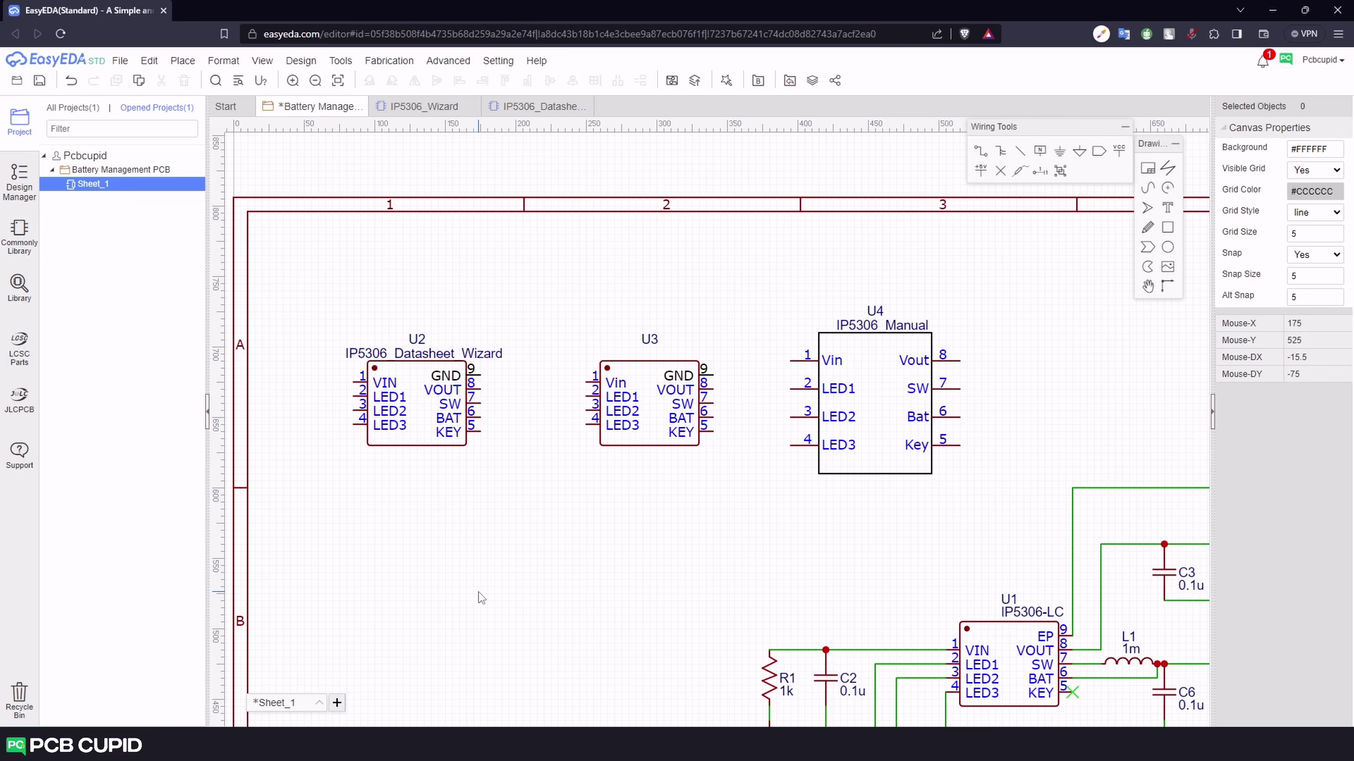
So, let’s create another symbol.
Here, instead of drawing the symbol from scratch, click on the symbol wizard icon on the toolbar. Which should give us a pop-up wizard to generate a custom symbol just by entering the pin configuration we need.
By default, it’s set to 12 pins, but it can be changed to a custom value by adding the pin names in order from the datasheet.
When you click ‘OK’, it will auto-generate a symbol.
This looks good, but let’s move these pins around on the left so it looks exactly like the part from the pre-existing library.
This will do a good job creating the symbol, but we still need to manually adjust the pin properties or other information we might want to change in the symbol.
Let’s quickly save this symbol and import it into our schematic.
It can be seen that this is very similar to the one from the existing library, and we even have the GND pin colored differently for easier understanding.
This method is a bit faster than the previous method?

EasyEDA: Crafting Symbol Through Datasheet Extraction Method
There is another method that’s even faster and more efficient for creating a symbol.
Let’s start again by creating a new symbol.
Here, we’ll ignore both the manual method and the wizard. Instead, click on the Datasheet Extraction icon on the top menu bar. This should bring up a pop-up that will generate a symbol just from the datasheet image. Which is super cool when you consider building a 50-pin IC manually.
This pop-up is pretty simple to use. Just select the type of IC you need and import the datasheet image. Here, let’s just paste a snippet that was captured from the datasheet.
You might face the issue if you use a color image or a low-resolution image. But it’s pretty easy to fix. Just paste a better-quality image with clearer text, which will fix the issue and auto-fill the complete pinout names for the IC.
Once you are sure about the pin names and numbers, click on ‘Next Step’. Here we can select the pin designator and name of the symbol and click on ‘OK’.

You can see that this created the symbol much faster than the previous two methods, without any manual modification. But this method is not guaranteed to work with all datasheets, although it works for most of the IC’s.
Now, let’s save this symbol and import it into our schematic editor.
Now it has successfully created a custom symbol for EasyEDA with very little effort.
But this symbol is just for representation and doesn’t say much about how the physical component is placed on the PCB.
This brings us to the end of the article. In the next article, we will discuss more about how to create a custom footprint, which will define the shape and dimension of the physical part within EasyEDA.
keep learning and keep creating!
If you have any queries, please drop them here
Also, you can watch the complete video tutorial here: