Creating Custom Symbols in KiCad

Let’s try to understand the more advanced features and tools KICAD has to offer and make custom symbols and footprints, along with which we’ll also optimize the PCB for cost-effective production.
Luckily for this circuit, we got all the symbols, and it looked pretty darn good, but there are situations where we might not have the proper symbols for the component.

If we search for the ESP 32 module in the schematic editor, we can see some esp32, but these are just the metal cap IC and not the module as a whole that is used for prototyping.

In this case, we might have to create a custom symbol, or we can search for the symbol online. There is a high probability that someone might have either already requested a similar symbol or they would have made a custom symbol and published it online.
It is better to make a custom symbol because it will reduce the unknown number of unknown variables that are introduced to the circuit, but getting help from the reliable community will reduce a ton of work down the road. Fortunately or unfortunately for this particular circuit, we might not need to create custom symbols So, we’ll recreate one of the existing symbols to learn how to use the symbol editor.
Creating Custom Symbol Libraries in KiCad
We’ll try to redo this Attiny IC symbol while following the library convention provided by KiCad. Let’s rely on the guidelines to build the symbol, even though it’s not a requirement. Because following this process makes it a lot easier to maintain a large number of custom libraries, which we’ll discuss further in the future video.
Now, to start, we can either use this icon on the toolbar or. Or you can just go to the kiCads project page and click on the symbol editor.

Here in the symbol editor, the navigation is pretty similar. We have a scroll to zoom in and zoom out, a middle click to, and a drag to pan. Not just the navigation; most of the tools are also very similar to what we saw in the schematic editor.

On the left, we have the list of libraries arranged in alphabetical order that already exist in KiCad. We can create a custom symbol and store it within any of these libraries, or we can modify an existing symbol.
But let’s try to not mess up the default library and symbol. Instead, let’s start with creating a new custom library. To do that, we can go to File and click on the new library.

In this popup, we can either select whether this library should be available on every single project that we’re going to make, or we just need this library to be on this particular project.
This really depends on how often you are planning to use the custom component. If you just need this project, select it, but if you need other projects as well, select Global.
Organizing Symbols in KiCad Libraries
After this selection, KiCad, we’ll ask for the location where you want to save the library. If it’s related to the project, save it in the same location as your project file; if not, create a folder in the desired location just for KiCad libraries and store it under it.

While naming, just don’t name the library as My_library or Custom_Library it can get really confusing once we start to make more of these, so try to give some thoughtful names, or the better option would be to follow the library convention provided by KiCad. Accordingly, let’s name this library “MUC_Microchip_Attiny85.”. Function, followed by the manufacturer, and finally the symbol series.

Since we have set up the library, we can create the symbol under this library. We can either click on File, click on a new symbol, or you can just click on this icon over here. This will create a new symbol and name the symbol, as the manufacturer’s part number for this symbol is Attiny85-20MU.
Next, select 1 unit. That’s because KiCad lets us create multiple unit’s for the same symbol. For example, let’s say you want to create an Arduino symbol.
Let’s break down the full module into three parts. where we can group the analog pins, digital pins, and power pins as 3 different units.
But this is a pretty simple circuit. So we’ll just stick to one.
And it is also better to keep all other settings to default. If you would like to know more about these features, you can read about them on the Kicad library convention document page.
Here we can see Kicad created the symbol with only the text and the designator; let’s move that aside using the shortcut ‘M’.

First, let’s set up the grid settings. In the previous videos, we did not bother much about the grid size, but to make a good custom library, try to keep the grid value at 1.27 mm, or 50 mils, because, as per KiCad standard library convention, all the pins should be 50 mils apart. By setting the grid to this value, we’ll make our job a lot easier when arranging the pins around the symbol.

Now, let’s start with creating an outline for our symbol. Use the rectangle tool to create the outline. Then use the keyboard shortcut ‘E’ and edit the rectangle. Here, let’s make sure this option is selected to fill the symbol with color. This fill helps us differentiate between the complex and the simple symbol. Currently, the dimension is a little random, but we can always adjust this later as we do more customization.

Anyway, let’s add a few pins to this symbol using the add-pin tool.
While adding the symbols, try to follow KiCad’s convention of grouping the pins. Where the power pins are at the top, ground at the bottom, input/control pins on the left, output/driver pins on the right, and finally arrange the GPIO or ports in order.

If we follow the rules for this symbol, we’ll have one pin on the top, one on the bottom, and the rest on the right of the symbol.
Currently, all the pins have the same name and the same property. To change this, you can either select the pin and right-click and then go to properties, or you can just use the keyboard shortcut ‘E’.
Here, we’ll name the pin.

Followed by the pin number, What the pins does and leave the rest of the things to default. Again, if you would like to know more about the rest of the settings, you can always refer to the library convention document.
Now, we need to do the same for each of the pins, if you don’t like the edit for individual pins. We can bulk edit all the pins at once using this tool.
Let me quickly update all the pin values. Finally, we can save this file by just hitting ctrl + s, which will save and automatically add it to our current project.
We can quickly check that by going to the schematic editor. Click on preference and then manage symbol libraries.
Since we have opted for the library only for this project, click on the project-specific library and here we can see that we have the library that we made.

If you would like to include this in every project, we can go to global libraries and add it here.
Adding External Libraries to KiCad
Since we are the library manager, let’s see how we can add external libraries to Kicad.
There are a few good places to search for the symbol; we would better go with SNAP EDA and Octopart. They both have a wide collection of symbols and support multiple design platforms other than Kicad.
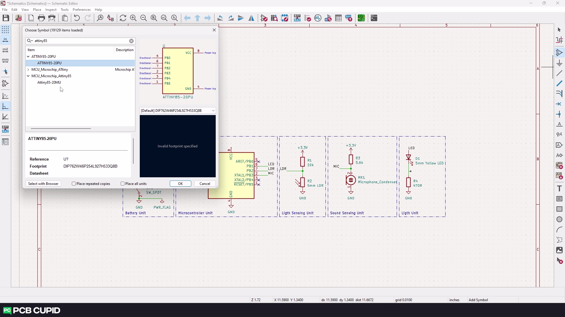
For now, let’s see how we can add to Snap EDA. Go to Snapeda.com and search for the part that we need. In this case, let’s try to search for the same part that we created, “Attiny85.”.

Once you find the part, you can download both the symbol and the footprint. Then unzip the folder.

If that’s done, go back to Kicad library manager and click on this folder icon. Here, navigate to the folder that we downloaded and open the symbol file.
This will add the folder to the global library.

Let’s go to the schematic editor and check if both symbols are available.
You can see we have both the custom library, the one we created, and the other from the Snap EDA.
For better understanding can watch the complete video tutorial here:
This brings us to the end of the article, Until then keep learning and keep creating!
If you have any queries, please drop them here